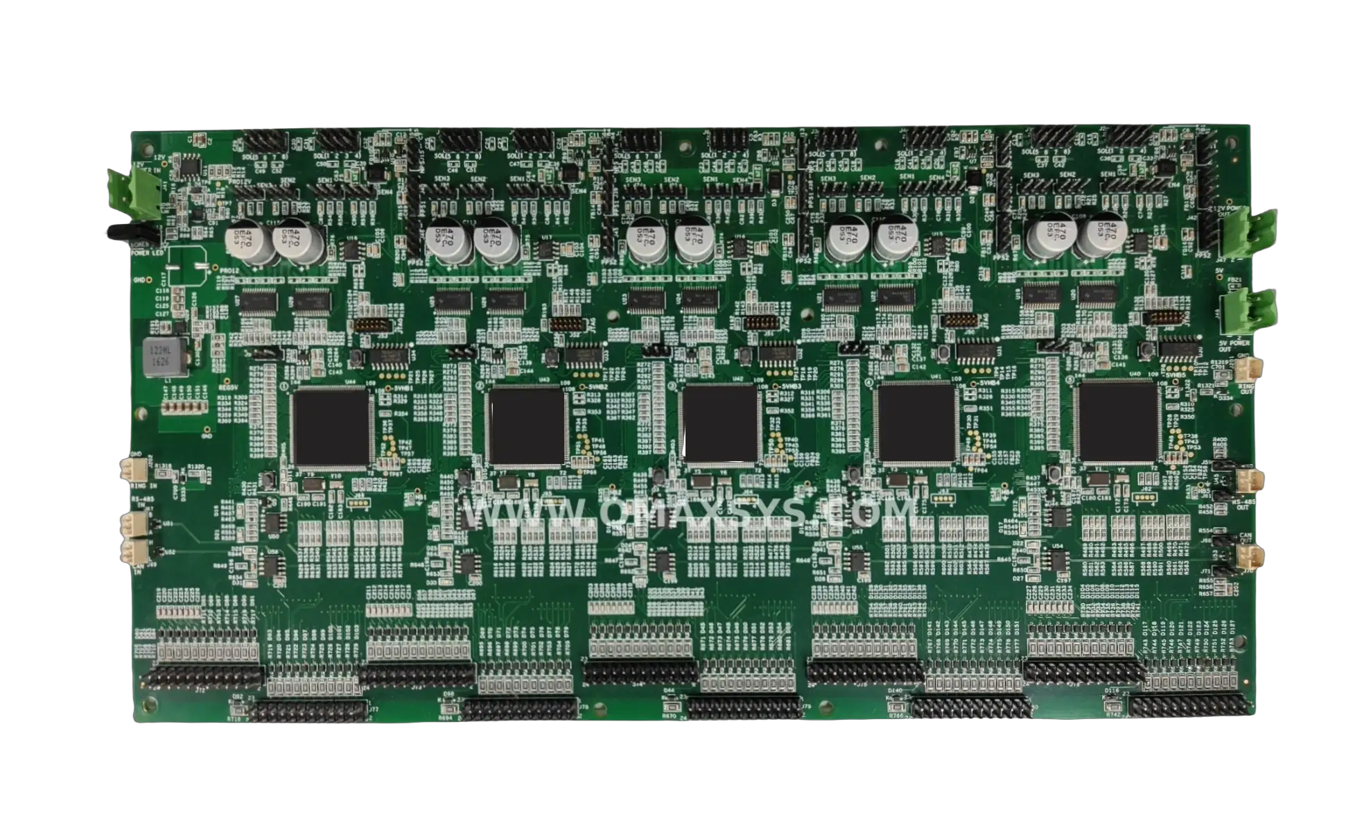
CAN FD-Based High-Density Industrial I/O Controller
Project Overview
Qmax Systems designed and delivered a CAN FD-based, high-density Industrial I/O Controller for a customer serving the automotive wiring harness manufacturing industry. The system replaces multiple high-end PLCs and I/O cards with a single, PC-programmable platform capable of testing hundreds of wire-to-wire connections across complex automotive wiring harnesses at production speed.
Qmax owned the complete development lifecycle — architecture, hardware design, firmware, PCB design, prototyping, and full Design Verification Testing (DVT) — carrying the product from customer requirement through to volume manufacturing. The customer has since manufactured and shipped 500+ units to automotive wiring harness manufacturers.
Product Brief
The Industrial I/O Controller is a massive digital I/O card supporting 240 discrete DIO channels, built around five automotive-grade microcontrollers operating in synchronization to manage this channel density within tight timing budgets. Each I/O channel is individually configurable over a CAN interface (FlexCAN 2.0B / CAN FD), letting operators define input, output, and test-signal behavior directly from a PC without reprogramming firmware.
The controller integrates analog inputs, pressure sensor / switch inputs, and LED and buzzer status indicators, and is architected to be cascaded so multiple cards can be linked together to scale I/O count for larger harness assemblies. Deployed on the factory floor, it performs rapid short/open testing across the many wire-to-wire connection combinations found in modern automotive wiring harnesses.
Scope of Work
Qmax Systems executed the complete product development lifecycle for this industrial I/O platform:
- End-to-end system architecture definition based on customer test requirements
- Hardware design of a 5-MCU synchronized, high-density digital I/O controller
- Firmware development in bare-metal C on ST SPC5 automotive microcontrollers (SPC5 Studio IDE)
- 6-layer, high-density PCB design (2,600+ components, 6,800+ pins)
- CAN FD interface and communication protocol implementation
- Analog front-end design for pressure sensor / switch inputs
- Prototype build and full Design Verification Testing (DVT)
- Ongoing design support through production ramp to 500+ units shipped
Engineering Challenges
Synchronizing 5 automotive-grade MCUs to manage 240 I/O channels without timing drift
Implemented a coordinated multi-MCU firmware architecture with deterministic scan cycles and shared timing references, ensuring all five SPC5 controllers maintain lockstep I/O operation across the full 240-channel matrix
Achieving very high component density (2,600+ parts) on a compact 6-layer board
Applied high-density PCB layout techniques across a 6-layer stack-up with optimized power/ground planes, micro-via routing, and disciplined component placement to fit 2,616 parts within a 75 sq. in. board area
Designing a configurable I/O architecture flexible enough for varied harness test patterns
Built a CAN FD-configurable channel model where each of the 240 DIO lines can be individually set as input, output, or test signal from a PC-based configuration utility — eliminating firmware changes for new test sequences
Maintaining signal integrity across a high pin-count, densely routed digital I/O design
Engineered controlled-impedance routing, dedicated return paths, and careful layer assignment for high-speed digital switching across 6,800+ pins while preserving clean signal transitions at production test speeds
Supporting cascading of multiple cards while preserving CAN bus reliability
Designed a dedicated cascading connector interface with robust CAN FD bus topology and termination strategy, allowing multiple I/O cards to be linked for expanded channel count without compromising communication integrity
Meeting industrial-grade robustness requirements for continuous factory-floor operation
Selected automotive-grade components, implemented multi-rail power distribution with protection, and validated the design through full DVT cycles simulating continuous factory-floor operating conditions
Integrating precision analog sensing alongside high-speed digital switching on one board
Partitioned analog and digital domains with dedicated front-end circuitry (instrumentation amplifiers, delta-sigma ADC) isolated from high-side switch noise, enabling accurate pressure sensor / switch monitoring on the same board as 240 digital channels
Minimizing full test-cycle time despite the combinatorial growth of wire-to-wire test combinations
Optimized multi-MCU parallel scanning firmware and fault detection logic to rapidly identify open/short conditions across harness connections, delivering production-speed test throughput despite the combinatorial test matrix
Hardware Components
ST SPC560B50L5C6E0Y
5× automotive-grade microcontrollers — synchronized multi-MCU control of 240 I/O channels (STMicroelectronics SPC5 family)
MCP2542FD
CAN FD transceivers for FlexCAN 2.0B communication and PC-based configuration interface
ISL81487
RS-485 transceiver for auxiliary serial communication
AD8221
Instrumentation amplifiers for precision pressure sensor / switch sensing
MCP3426
16-bit delta-sigma ADC for analog input conversion
TPS4H160
Multi-channel high-side smart power switches for digital output driving
TPS563208, MIC5377
Buck regulators and LDOs for multi-rail power distribution
AT24C08C
I2C EEPROM for configuration and calibration storage
Interfaces & Protocols
CAN FD (FlexCAN 2.0B)
Primary configuration and control interface — field-programmable I/O behavior from a host PC
RS-485
Auxiliary serial communication
Digital I/O
240 configurable channels for wiring harness test connections
Analog Inputs
Pressure sensor / switch monitoring
I2C
EEPROM configuration and calibration storage
PC Programming Interface
Field configuration of I/O behavior from a host PC without firmware reprogramming
Cascading Connector
Links multiple I/O cards for expanded channel count on larger harness assemblies
Status / Indicator
LEDs and buzzer for pass/fail and operational feedback
Firmware & Software
Bare-metal C firmware developed on ST SPC5 automotive microcontrollers using SPC5 Studio:
Multi-MCU Synchronization
Coordinated firmware for five SPC560B50 controllers managing synchronized 240-channel I/O scanning without timing drift
CAN FD Protocol Stack
FlexCAN 2.0B / CAN FD implementation for configuration commands and data exchange with the host PC
PC Configuration Utility Integration
Integration with a PC-based configuration tool for field-programmable I/O channel behavior
Analog Signal Acquisition
Calibration routines and acquisition logic for pressure sensor / switch inputs via MCP3426 ADC
Fault Detection Logic
Open/short circuit identification across harness wire-to-wire connection combinations
Status Indication
LED and buzzer control logic for pass/fail test feedback on the factory floor
DVT Validation
Firmware validated across full Design Verification Testing test cycles before production release
Technical Specifications
Summary
Qmax Systems delivered a complete CAN FD-based Industrial I/O Controller from architecture through production support, giving the customer a single, PC-programmable platform that replaces multiple high-end PLCs and I/O cards. With 240 configurable digital I/O channels driven by five synchronized automotive-grade microcontrollers, the system performs fast, reliable connection testing across complex automotive wiring harnesses.
The product has scaled to 500+ units shipped to automotive wiring harness manufacturers, demonstrating Qmax Systems' capability to take high-density embedded controller platforms from concept through architecture, hardware, firmware, PCB design, prototyping, and DVT to volume production.