Power Engineering Where Current Density, Isolation and Heat Decide the Outcome
For 29 years Qmax Systems has designed power conversion, distribution and storage hardware — from architecture and topology selection through magnetics, busbar and interconnect design, thermal simulation, high-voltage safety and protection coordination, PCB layout, bring-up and certification, to volume production. Power is one of four disciplines in our full product hardware design practice, which is why the control, sensing and communications sections of a converter are designed alongside the power stage rather than after it.
Power electronics fails physically, not logically. A schematic can be electrically correct and the product still fail because the busbar runs hot, the creepage distance was short at altitude, the switching loop rings into the gate drive, or the protection did not discriminate and a single fault took down the whole branch. Those are decisions made in the copper, the stack-up and the clearance table — and they are resolved in simulation and layout, before the first board is fabricated.
The work spans a wide range: 48 V BLDC drives and 12-cell balancers at one end, and 3 kV / 100 A power modules, 300 kW SiC inverters, 800 V on-board chargers and UL-certified 45 kW rack PDUs shipped in the hundreds at the other. Every program is owned by senior engineers from architecture through manufacturing handover, and you own 100% of the resulting intellectual property at every milestone.
Architecture & Loss Budget
Topology selection, loss and efficiency budget, device and thermal sizing
Heavy copper stack-ups, thermal via arrays, creepage and clearance per IEC 60664-1
Applications & Real-World Project Experience
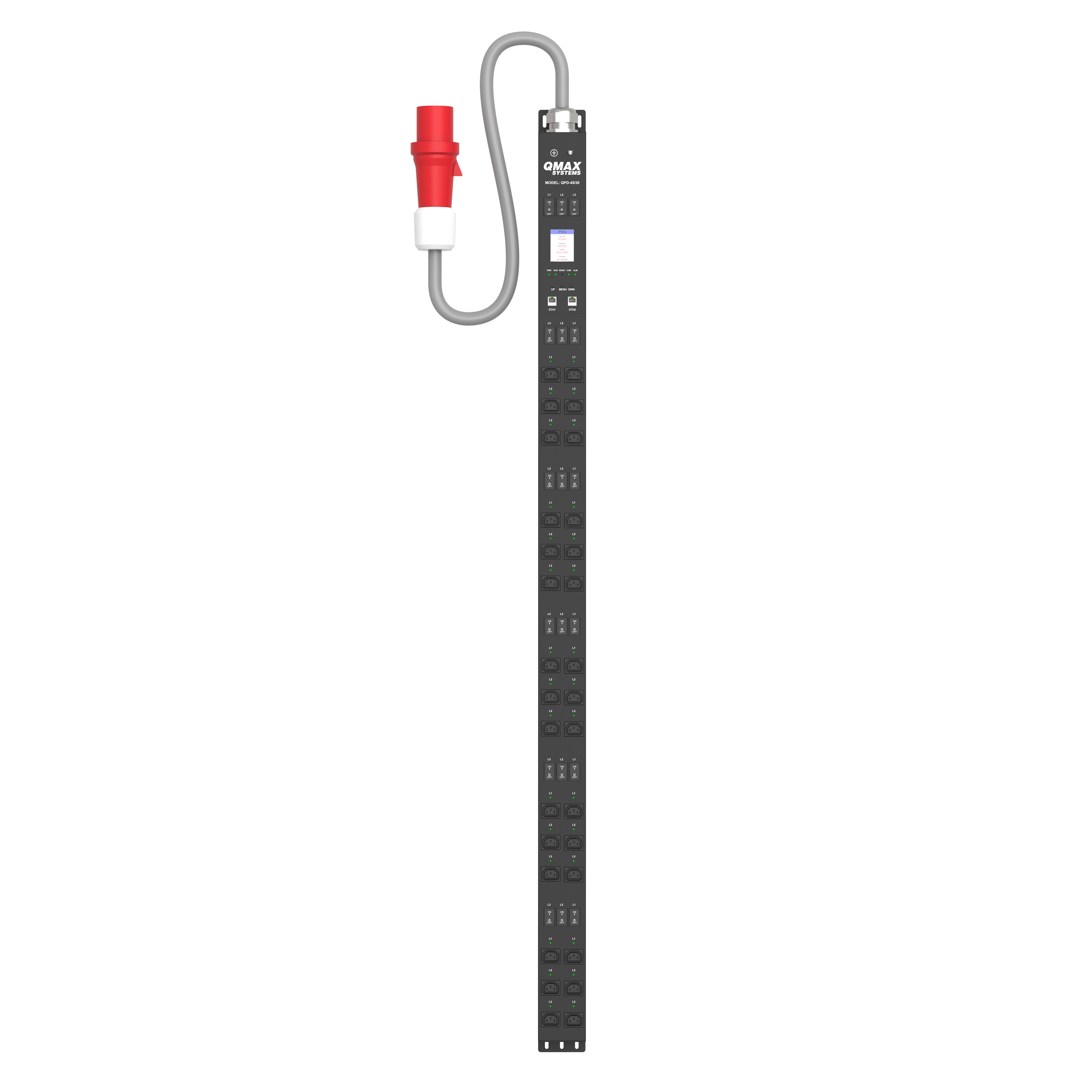
This is a vertical, 72-inch 0U rack-mount intelligent Power Distribution Unit on a mains-isolated three-board architecture, delivering 415 VAC, 45 kVA, 3-phase power to 30 individually metered and switched C13 outlets with ~1% accuracy. An embedded Linux processor bridges telemetry to a dual-redundant Ethernet network, enabling remote monitoring and switching.
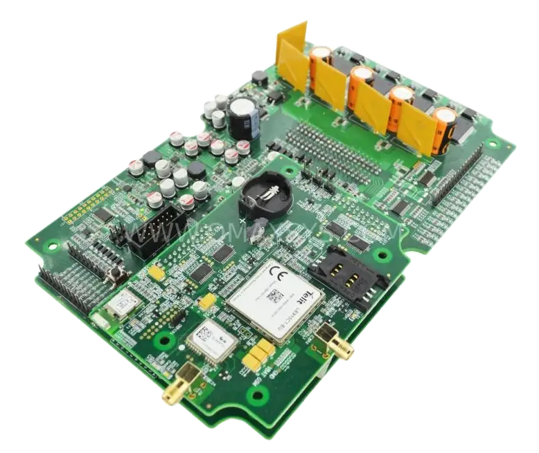
This is a high-voltage motor controller ECU built around a multi-phase IGBT/MOSFET power stage rated for 450V bulk capacitance, driving heavy-duty three-phase output terminals for traction or industrial motor loads. An onboard microcontroller and gate-driver circuitry manage switching and protection, with headers for CAN signaling and sensor feedback.
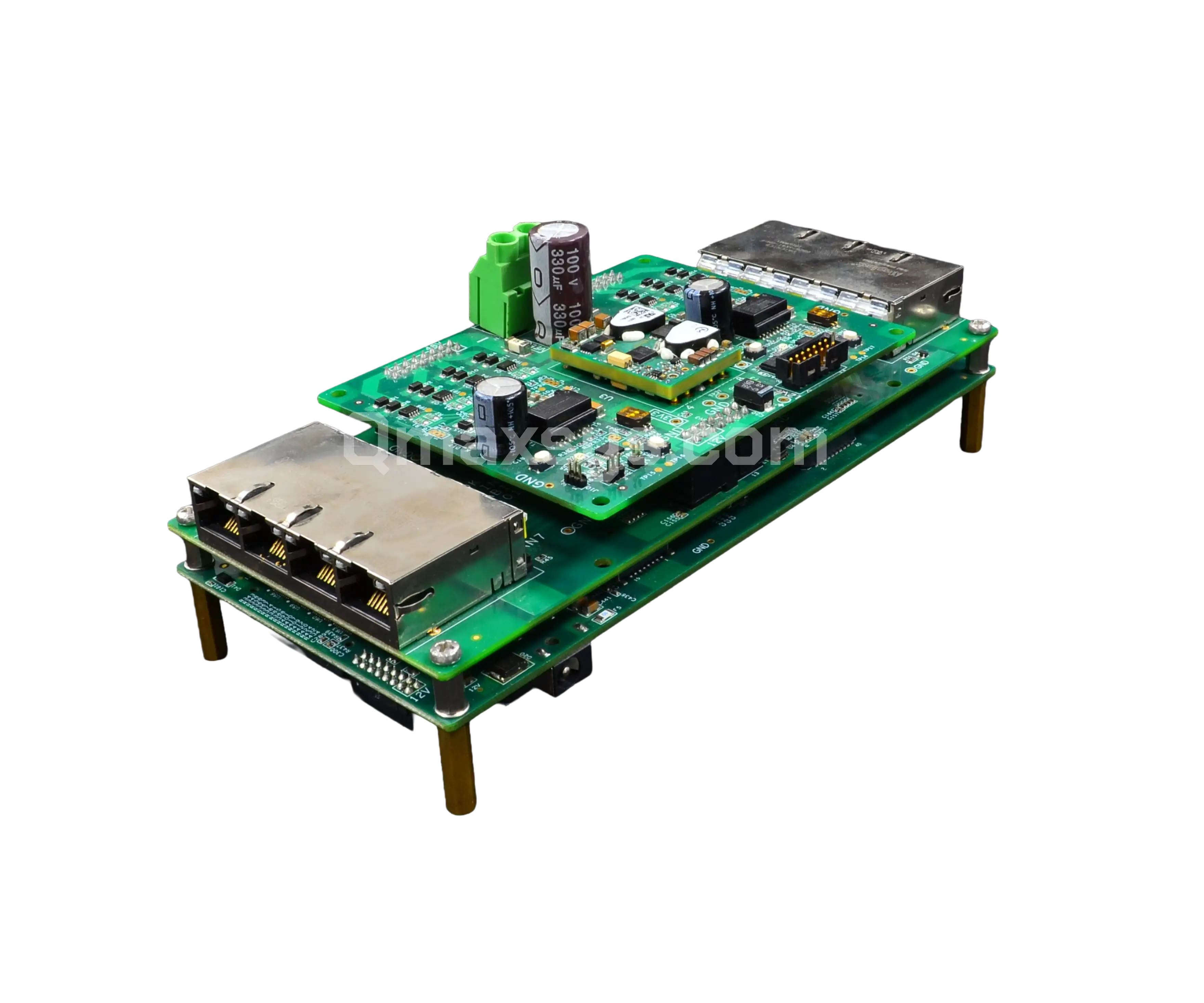
This is a dual-channel MPPT solar power management board that regulates and converts solar MPPT inputs and dual SMPS rails into a stable output feeding a battery expansion bank. It integrates PoE backhaul, standby/auto power-enable control, and an MCU-driven I2C monitoring interface for intelligent power routing and charge management off-grid.
Click to zoom
1 / 9
High-Voltage Safety and Protection Coordination
Insulation Coordination Before Layout
Clearance and creepage are not clearances you check at the end — they are derived from working voltage, overvoltage category, pollution degree and altitude, and they constrain where every component can sit. We build that table first, to IEC 60664-1, and lay out against it.
Working voltage, overvoltage category and pollution degree established up front
Basic, supplementary and reinforced insulation decided by function
Altitude derating applied where the product is deployed high
3D validation of distances inside compact enclosures
Conformal coating and potting where physical distance is unavailable
Protection That Discriminates
Fitting a breaker is not protection. Protection is a coordinated set of devices where a fault trips the smallest one able to clear it, so the rest of the system stays up. That coordination is designed, then verified by test.
Discrimination between main, branch and load-level devices
Hydraulic-magnetic breakers where ambient-independent tripping matters
Electronic per-outlet and per-branch trips for everyday overload
HV DC fusing selected on let-through energy, not just rating
Pre-charge circuits to limit capacitive inrush on bus connection
Floating DC Systems and Interlocks
An ungrounded high-voltage DC bus will not blow a fuse on a first earth fault — it will simply sit there, degraded and undetected, until a second fault makes it dangerous. That is why insulation monitoring exists, and why interlocks are engineered rather than fitted.
Insulation monitoring devices on floating DC battery and drive buses
Interlock chains with door, panel and connector position sensing
Active discharge of DC-link capacitance on shutdown and fault
Defined safe-state behavior on loss of control power
Protective earthing, bonding and touch-current control
Governing Standards by Equipment Class
Getting the standard right matters as much as passing it. A traction inverter, a rack PDU and a battery rack are governed by three different standards with three different insulation and protection philosophies. Establishing which applies is an architecture decision, taken at the start of the program.
Hazard-based safety for audio, video and ICT equipment
Circuit breakers and supplementary protectors
UL 489, UL 1077, EN 60934
Overcurrent protective device qualification
Battery systems for stationary and motive use
UL 1973
Batteries for use in energy storage and light rail
Automotive electronics
CISPR 25 · AIS-004 (Part 3) · ISO 26262
Vehicle EMC and functional safety with ASIL traceability
Immunity, all classes
IEC 61000-4 series
ESD, surge, electrical fast transient, dips and interruptions
Qmax-designed products have completed formal certification to UL489 and UL1077 on the rack PDU program, ARAI for the automotive kneeling and levelling system, FCC Part 15 Class A and Class B, FCC Part 18 Class A for industrial RF, SAR, CE and UL safety listing. Qmax manages the certification program, holds the technical file and the test evidence, and has taken products through on first submission.
Why Choose Qmax for Power Electronics Design
We Own the Whole Power Path
Most design houses stop at the board edge. We design the laminated busbars, the current collectors, the terminations and the interconnect that actually carry the current — because at hundreds of amperes the copper is the circuit, and a board designed in isolation from it will not hold its thermal budget.
Kilowatts With Certification Attached
High power is only half the claim. Our rack PDU program is UL489 and UL1077 certified with hundreds of units shipped; the bus levelling system is ARAI certified at 10,000 units. We manage the certification program, hold the technical file, and have taken products through on first submission.
Thermal Resolved Before the Prototype
Junction temperature is designed, not measured after the fact. Copper weight, thermal via arrays, IMS and high-Tg substrates, cold plates and custom heat sinks are selected against a simulated thermal budget with derating applied, so the first build runs inside its limits instead of revealing them.
Protection That Coordinates
We design discrimination, not just devices — so a fault trips the smallest protective element that can clear it and the rest of the system stays up. On the rack PDU that meant 40 A hydraulic-magnetic branch breakers coordinated against per-outlet electronic trips at 15 A, verified by test rather than assumed from datasheets.
Magnetics as a Design Variable
Off-the-shelf magnetics constrain the converter around them. We design custom inductors and transformers — wound and planar, including planar windings realized in the PCB stack-up — specifying core material, winding geometry and litz-wire gauge against the switching frequency, core loss and leakage inductance the topology actually needs.
ISO 9001 and ISO 13485 Certified Process
High-voltage mistakes are expensive to find late and dangerous to find in the field. Qmax operates ISO 9001 and ISO 13485 certified quality systems, with defined internal process steps and review gates built to catch errors before a design reaches fabrication.
Get a Complimentary Consultation with Our Power Electronics Experts
A one-hour session with a Qmax Systems Senior Hardware Architect. Bring a converter that runs hot, a busbar you cannot cool, a clearance table that will not close in the enclosure you have, or protection that trips the wrong device. Practical and engineering-driven — no sales pitch. We can sign an NDA beforehand.
What power levels and voltage classes does Qmax Systems design to?
Qmax Systems designs across the practical span of power electronics: from 48 V BLDC drives and 12-cell balancers, through 415 VAC three-phase distribution and 800 V EV traction and charging buses, up to 1000 V DC battery racks, 3 kV / 100 A power modules and 300 kW silicon carbide inverters. Neither end is a limit. The discipline is the same at every point on it — current path, isolation coordination, thermal margin and protection — so a new voltage or power class is scoped against that engineering rather than against a fixed catalog.
Does Qmax Systems design battery packs and energy storage systems?
Yes, including the physical power path most design houses do not touch. Qmax Systems designs battery module and rack electromechanical hardware — laminated busbars, cell current collectors, and cell voltage and temperature sense flex harnesses — alongside BMS integration with active and passive balancing, State-of-Charge estimation and multi-stage protection. Recent work includes a multi-year grid-scale storage program on a 1000 V DC class rack architecture, and packs in LiFePO4, Li-ion and lithium titanate chemistries.
How does Qmax Systems manage thermal dissipation in high-density power modules?
Thermal design is resolved in simulation before prototyping, with junction temperatures held inside derated limits rather than discovered at bring-up. The toolkit is heavy-copper traces and busbars, thermal via arrays, Insulated Metal Substrate and high-Tg FR-4, custom heat sinks with simulated airflow, and liquid-cooled cold plates where power density demands them. Copper weight and substrate are chosen from the current density and the temperature rise you need to hold, not from habit.
What is Qmax Systems' experience with wide-bandgap SiC and GaN devices?
Qmax Systems designs with silicon carbide and gallium nitride devices in high-frequency converters to shrink magnetics and raise efficiency, including a 300 kW SiC traction inverter and a 3 kV / 100 A SiC power module board. The engineering focus is managing the consequences of fast edges: high dv/dt and di/dt injecting common-mode current across isolation barriers, gate-loop parasitic inductance causing ringing, and the EMI that follows. That is handled through gate-drive design, commutation-loop layout and snubber selection.
How does Qmax Systems ensure safety in high-voltage 800 V and above designs?
Through insulation coordination applied as a layout constraint rather than a final check. Working voltage, overvoltage category, pollution degree and altitude are established first, and the resulting clearance and creepage table — built to IEC 60664-1 — determines where every component can sit. That is combined with galvanic isolation of control circuitry, active discharge of DC-link capacitance on shutdown and fault, defined safe-state behavior on loss of control power, and 3D validation of distances inside compact enclosures.
What is protection coordination, and why does it matter?
Coordination, or discrimination, means a fault trips the smallest protective device capable of clearing it, so the rest of the system keeps running. Fitting a breaker is not protection; coordinating main, branch and load-level devices is. On the Qmax rack PDU, 40 A hydraulic-magnetic branch breakers handle genuine fault conditions while per-outlet electronic trips at 15 A absorb everyday overload — so a single misbehaving load does not de-energise its whole branch. Coordination is designed, then verified by test.
Why do hydraulic-magnetic breakers get specified instead of thermal-magnetic?
Because the trip point does not drift with ambient temperature. A thermal-magnetic breaker relies on a bimetallic element, so its characteristic shifts as the surrounding air heats up — which is exactly what happens inside a loaded server rack or a sealed enclosure. A hydraulic-magnetic breaker trips on current through a solenoid and a damping fluid, giving a repeatable curve across the operating temperature range. On equipment that must coordinate predictably, that repeatability is worth the cost difference.
How does Qmax Systems handle insulation monitoring on floating DC systems?
An ungrounded high-voltage DC bus will not clear a fuse on a first earth fault — it simply continues running with degraded insulation until a second fault creates a hazard. Qmax Systems designs in insulation monitoring devices that continuously measure bus-to-earth resistance on floating battery and drive buses, alarming before the second fault can occur. This is combined with interlock chains sensing door, panel and connector position, and protective earthing and bonding with touch-current control.
How does Qmax Systems achieve high efficiency in AC-DC conversion?
Through topology choice and synchronous rectification rather than brute-force component selection. Bridgeless totem-pole power factor correction removes a diode bridge drop from the input path; synchronous rectification replaces output diodes with actively driven devices to cut conduction loss; and resonant LLC, CLLC and phase-shifted full bridge stages keep switching soft across the operating range. Qmax Systems regularly designs supplies reaching 80 PLUS Titanium efficiency levels, with DC-DC stages above 96%.
Does Qmax Systems design custom magnetic components?
Yes, and it is often what makes the topology viable. Off-the-shelf magnetics constrain the converter around them. Qmax Systems designs custom inductors and transformers — wound and planar, including planar windings realized directly in the PCB stack-up — specifying core material, winding geometry and litz-wire gauge against the switching frequency, ripple, core loss and leakage inductance the design actually requires.
Does Qmax Systems design laminated busbars and high-current interconnect?
Yes. At hundreds of amperes the interconnect is a circuit element, not a wire. Qmax Systems designs laminated busbar stacks, cell current collectors and high-current terminations, resolving current density and thermal spread, commutation-loop inductance, insulation coordination between layers, and manufacturability of the lamination and forming. This work includes proprietary copper busbar technology developed in-house for a 3 kV / 100 A silicon carbide power module.
How accurate is Qmax Systems' power and energy measurement?
Qmax Systems designs metering to approximately 1% accuracy on voltage, current, power, power factor and energy, verified per unit rather than assumed. On the rack PDU that meant five STPM34 metering front ends polled in real time over SPI, with per-channel gain and offset calibration coefficients stored in flash and logged per unit for production traceability — achieved on a board mounted directly against 30 switching mains relays.
Can Qmax Systems take a power product through certification and volume manufacturing?
Yes, and it has. Qmax Systems manages the certification program and holds the technical file: the rack PDU is UL489 and UL1077 certified with hundreds of units shipped, and the automotive kneeling and levelling system is ARAI certified at 10,000 units produced. Volume work covers NPI, test jig and test plan development, per-unit calibration and traceability, epoxy encapsulation where the environment demands it, and manufacturing coordination through to shipment.
Does Qmax Systems provide board bring-up and power debug?
Yes. Hardware, layout and firmware engineers work in the same delivery center, so bring-up is handled by the team that designed the board. Power debug covers power-up sequencing and pre-charge verification, gate-drive waveform and dead-time validation, switching-node ringing and snubber tuning, thermal imaging under load, efficiency mapping across the operating range, protection and fault-injection testing, and conducted and radiated emissions pre-scans.
Can Qmax Systems take over a power design that is failing thermally or on emissions?
Yes, and it is a common way our engagements begin. Typical work includes independent review of the schematic, layout and thermal design, measurement of actual junction and busbar temperatures against the intended budget, locating the loss or the coupling path, and a corrective package addressing copper weight, cooling strategy, commutation-loop layout, snubber and filter design, or protection coordination. Where a clearance or standards problem is the real issue, that is established first — there is no point optimizing a design against the wrong standard.