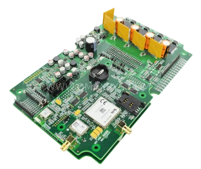
EV Vehicle Control Unit (VCU) – Demo Platform
Project Overview
Qmax Systems architected, designed, and delivered a fully functional EV Vehicle Control Unit (VCU) demo platform for a customer building connected, electrified mobility solutions across two-wheeler and four-wheeler EV platforms. Qmax owned the complete development lifecycle — architecture, hardware design, firmware, PCB design, prototyping, and full Design Verification Testing (DVT) — carrying the product from a blank-sheet requirement through to working prototypes.
The customer now uses the platform as a reference design to showcase full-fledged VCU and connectivity gateway capabilities to automotive OEMs and market leaders, and has carried the architecture forward into subsequent projects.
Product Brief
The EV VCU demo platform is a two-board embedded system built around an ST SPC560B60 automotive-grade microcontroller, targeted at low-cost EV applications spanning electric two-wheelers and four-wheelers. A dedicated ECU board hosts the microcontroller, power regulation, and load-driving peripherals — including a dual-channel H-bridge motor driver, a 16-channel high-side switch driver, and a 24-input Multiple Switch Detection Interface (MSDI) — while a companion radio board adds Bluetooth Low Energy, cellular, and GNSS connectivity across 8+ vehicle and communication interfaces.
The two boards interface through a board-to-board mating connector, and Qmax validated and released tested firmware binaries covering every hardware interface, letting the customer layer its own connected-vehicle demo application directly on top.
Scope of Work
Qmax Systems executed the complete embedded development lifecycle for this EV VCU reference platform:
- End-to-end embedded system architecture definition from customer requirements
- Hardware design of a 2-board EV VCU platform (ECU board + radio/connectivity board)
- Bare-metal C firmware development on SPC5 automotive microcontrollers using SPC5Studio IDE
- PCB design and layout across a 6-layer main board and a 4-layer radio board
- Integration of BLE, cellular, and GNSS radio modules with antenna matching circuits
- Power architecture design with reverse-polarity, over/under-voltage, and ESD/EMI protection
- Prototype build and full Design Verification Testing (DVT) of all interfaces
- Release of validated test firmware binaries to the customer for demo application development
Engineering Challenges
Selecting a low-cost automotive MCU platform capable of covering the full breadth of VCU functions for entry-level EVs
Selected the ST SPC560B60 automotive-grade MCU with 5× CAN, 8× UART, 4× SPI, and I2C — providing sufficient peripheral capacity for VCU, gateway, and load-driving functions on a single cost-optimized platform
Integrating multiple wireless radios (BLE, cellular, GNSS) alongside high-current motor and switching loads on one platform
Split the design into a dedicated ECU board for load driving and a companion radio board for BLE, LTE Cat 1, and GNSS, with RF-conscious layout and antenna matching on the connectivity board
Splitting the design across two boards while preserving signal integrity through a board-to-board mating connector
Engineered a board-to-board mating connector interface with controlled impedance routing and validated signal integrity for SPI, UART, and power rails across the ECU and radio boards
Designing robust input protection to survive automotive transients — load dump, over/under-voltage, and reverse polarity
Implemented MAX16126 automotive input-protection and supervisory ICs with reverse-polarity, over/under-voltage, and ESD/EMI protection across vehicle power and field inputs
Driving mixed load types — H-bridge motor outputs, high-side relays/actuators, and 24 switch inputs — from a single MCU over SPI
Integrated VNH5019ATR-E dual-channel H-bridge, TLE75080ESHXUMA1 16-channel high-side driver, and TIC12400 MSDI ICs with SPI-based control firmware for unified load management from the SPC560B60
Handling 1.8V-tolerant cellular module signaling alongside 3.3V/5V board logic
Designed level-appropriate signal conditioning and interface circuitry between the Telit LTE module's 1.8V I/O and the board's 3.3V/5V logic domains
Validating every radio and peripheral interface independently within DVT ahead of customer handoff
Developed interface-by-interface hardware validation firmware with PC-terminal debug logging, completing full DVT coverage of CAN, LIN, UART, SPI, BLE, cellular, GNSS, and all load drivers before release
Keeping the design flexible enough to serve as a general-purpose reference platform rather than a single fixed product
Architected a modular two-board platform with validated test firmware binaries released to the customer, enabling flexible demo application development for both 2W and 4W EV programs
Hardware Components
SPC560B60
ST automotive-grade microcontroller (Power Architecture, 144-pin LQFP) — 5× CAN, 8× UART, 4× SPI, I2C central control
BlueMod+S50
Telit Bluetooth Low Energy module with internal antenna for connected-vehicle demo connectivity
LE910-C1
Telit LTE Cat 1 cellular module with external antenna and SIM interface
SL869-T3I
Telit GNSS module for location tracking
VNH5019ATR-E
Dual-channel H-bridge motor driver for EV load actuation
TLE75080ESHXUMA1
16-channel high-side smart switch driver for relay and actuator outputs
TIC12400
24-input Multiple Switch Detection Interface (MSDI) ICs for vehicle switch scanning
MAX16126
Automotive input-protection and supervisory ICs for transient and polarity protection
Interfaces & Protocols
CAN Bus (Multiple Channels)
Vehicle network communication
LIN Bus
Peripheral and body electronics communication
UART
Cellular, GNSS, and BLE module communication and debug
SPI
MSDI switch inputs, H-bridge, and high-side driver control
I2C
On-board I/O expansion
Board-to-Board Mating Connector
Links the ECU board and radio/connectivity board
14-Pin JTAG
Debug and programming interface
ECU Connector
Vehicle power, switch inputs, and load-driving outputs
Firmware & Software
Bare-metal C firmware on SPC5 automotive MCU developed using SPC5Studio IDE:
Peripheral Driver Development
Drivers for CAN, LIN, UART, SPI, and I2C peripherals on the SPC560B60 platform
Load Control Firmware
H-bridge and high-side switch control with SPI-based PWM and direction control
MSDI Switch Scanning
Switch-input scanning and debounce firmware across 24 MSDI channels
Radio Module Bring-Up
BLE, cellular, and GNSS module integration and communication stack bring-up
Watchdog & Fault Recovery
Watchdog timer configuration (62 ms – 72 s) and fault-recovery logic
Interface Validation Firmware
Interface-by-interface hardware validation with PC-terminal debug logging for DVT
Test Binary Release
Validated test firmware binaries packaged and released for customer demo application development
Technical Specifications
Summary
Qmax Systems delivered a complete EV VCU demo platform — spanning architecture, hardware, firmware, PCB design, and DVT — built around a low-cost automotive microcontroller and a full suite of vehicle and wireless interfaces. The validated, two-board reference design gave the customer a working platform to demonstrate VCU capabilities to automotive OEMs and to carry forward into future EV programs.
With BLE, LTE Cat 1, and GNSS connectivity alongside CAN, LIN, motor driving, and 24-channel switch detection, the platform demonstrates Qmax's ability to deliver connected automotive embedded systems from blank-sheet requirements through validated prototypes ready for customer demo application development.